Freezer Room & Low Stage Pkg
The site features a substantial freezer room, measuring 1,076 m², operating at -20°C and using a 120 kW refrigeration system. This system employs CO₂ (R744) as the refrigerant in four direct expansion evaporators, each equipped with Danfoss electronic expansion valves. For defrosting, the system uses warm glycol, which is heated by repurposing waste heat generated from the freezer room’s refrigeration process, enhancing energy efficiency.
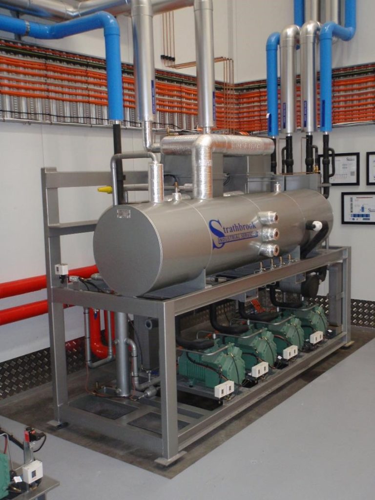
Designed and built by Strathbrook Refrigeration Services, the refrigeration package comprises four Bitzer piston compressors in a single circuit. The lead compressor utilizes speed control to better match load demands. The system includes an open flash intercooler and liquid receiver, which maintains liquid CO₂ at -5°C. Discharge gas from the oil separator is condensed within the liquid receiver, with vapor recondensed through two high-pressure plate heat exchangers before returning to the receiver. This design creates a continuous loop, ensuring efficient operation and reliable liquid CO₂ supply.
The system operates as a CO₂ cascade cooling setup, with both stages utilizing direct expansion CO₂. Heat for the glycol defrost system is sourced from the low stage discharge gas via a dedicated plate heat exchanger. Additional heat management involves warming the suction vapor through another set of plate heat exchangers, maintaining optimal compressor operating conditions by keeping the compressor oil systems warm and free of liquid droplets. This arrangement also increases the compressor discharge gas temperature, maximizing heat recovery while ensuring efficient and stable operation of the refrigeration package.
Coolroom / Loading Dock / High Stage Pkg
The facility includes a spacious cool room measuring 1,159 m², maintained between 2 to 4°C using four direct expansion air defrost evaporators equipped with electronic TX valves. This system operates at a capacity of 120 kW at -4°C, ensuring optimal storage conditions for temperature-sensitive goods.
Adjacent to the cool room, the loading dock area features three direct expansion CO₂ evaporators serving two dock areas, adding an additional 60 kW capacity. These evaporators share the same suction group as the cool room system, optimizing energy use and operational efficiency within the facility.
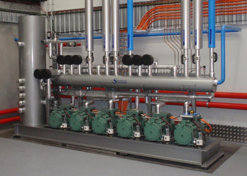
The rack package, engineered by Strathbrook Industrial Services, incorporates six Bitzer piston compressors configured in a split suction design. Three compressors manage the high stage for the cascade freezer system, while the remaining three compressors cool both the cool room and the dock areas. This design necessitates a trans-critical CO₂ system with a maximum operating pressure of 130 bar, ensuring robust performance and reliability in demanding operational conditions.
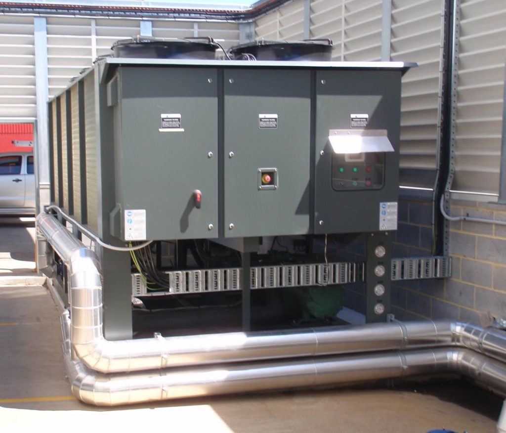
A critical component of the system is the Guntner Gas Cooler located on the outside condenser deck, boasting a capacity of 440 kW. This unit is equipped with eight 900 mm EC fans and features a stainless steel coil block with epoxy-coated aluminum fin stock. Fan speed is dynamically controlled by the Danfoss system based on gas cooler exit temperature, allowing for energy-efficient operation by adjusting fan speed according to ambient conditions. The system also includes a vertical liquid receiver with Danfoss electronic control valves to maintain optimal system pressures. Additionally, a suction header/shell and tube heat exchanger warms returning suction vapor and sub-cools liquid CO₂, enhancing overall system efficiency and improving compressor performance under varying load conditions.
High Demand Unit / Australian Design Patent
Strathbrook Refrigeration Services has developed a patented approach to enhance the efficiency of trans-critical CO2 systems, which typically face reduced efficiency in high ambient temperatures above 19°C. Unlike conventional systems that require additional compressor capacity during peak ambient conditions, Strathbrook’s design incorporates a separate high-demand unit. This unit, a 400 kW water chiller equipped with two Bitzer CSH 75 series screw compressors using R134a, functions to cool the refrigerant leaving the CO2 gas cooler. By maintaining lower refrigerant temperatures, this setup enables the CO2 system to operate similarly to its efficiency during cooler weather conditions, even when ambient temperatures are high.
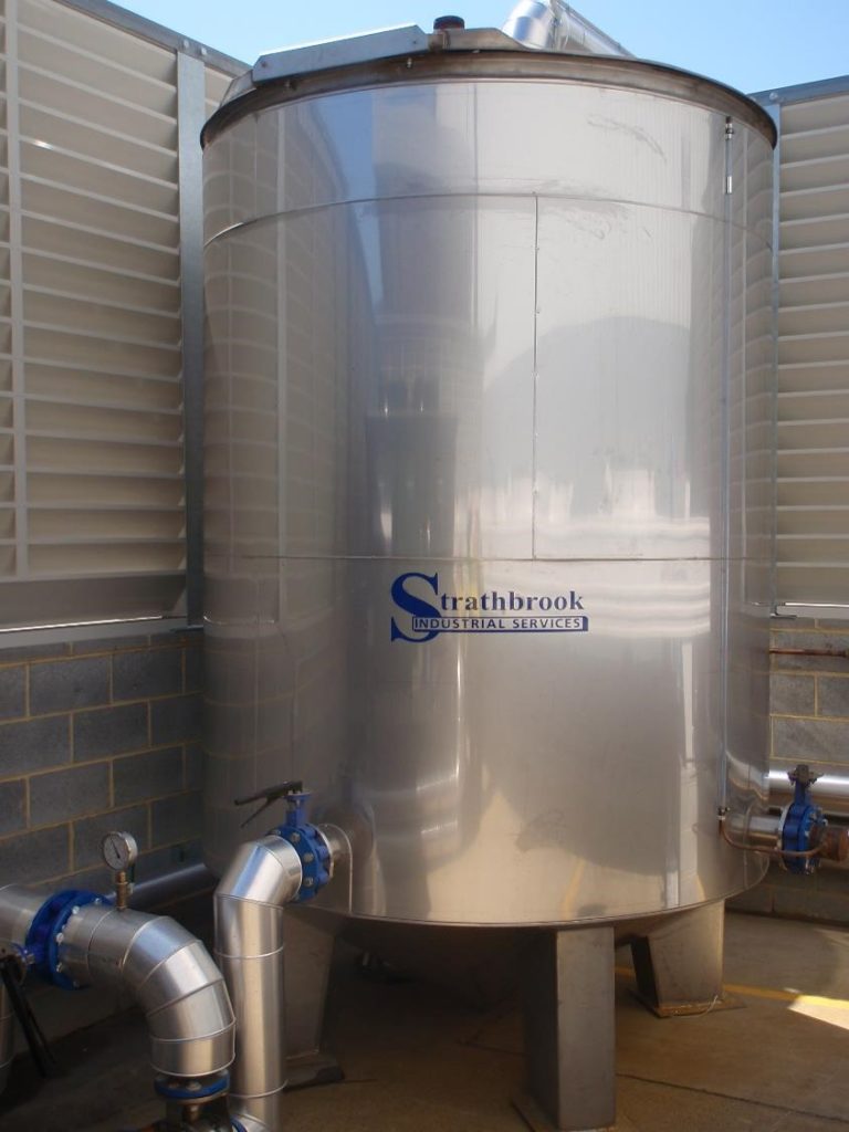
The high-demand water chiller supplies chilled water at 17°C to a pair of high-pressure plate heat exchangers situated at the gas cooler outlet. This chilled water then flows into a 9,000 L insulated storage tank before returning to the chiller. The tank’s thermal storage capacity allows the chiller to operate efficiently for extended periods during low-demand times, cycling off when thermal storage in the tank maintains optimal conditions.
Due to the comparatively higher suction temperature of the water chiller in contrast to the CO2 system, the overall system’s coefficient of performance (COP) increases significantly during high ambient conditions. This integrated approach not only reduces the operating pressure of the CO2 system but also minimizes the motor input power required for the high-stage compressors, thereby enhancing total system efficiency across varying ambient temperatures.
Control System
The system is managed by a Danfoss 255 System controller, integrating electronic input/output cards to facilitate continuous data exchange with the microprocessor. This setup enables comprehensive monitoring and control of all operational facets. Dedicated computer cards oversee specific components like the electronic motor control valves for the liquid receiver and electronic expansion valves. The controller interfaces with gas detectors, variable speed drives, room temperature sensors, and system pressure and temperature monitors, allowing for real-time performance monitoring both on-site and remotely via internet connectivity.
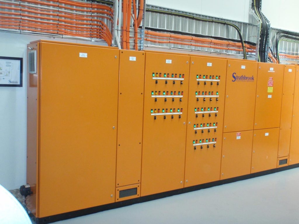
To ensure uninterrupted operation, particularly during power outages, an Uninterrupted Power Supply (UPS) is incorporated within the electrical panel (Figure 9). This UPS not only safeguards the integrity of the control system by maintaining power continuity but also supplies power to the emergency cooling system when needed.
Electrical And Lighting System
The electrical panel, crafted by Strathbrook Electrical Services, houses the Danfoss control system alongside essential power and safety circuits. Due to slight limitations in available power, a dual supply system was devised to meet the project’s total power requirements. Additionally, a load shedding mechanism was implemented to manage current shortages by shutting down evaporators in a controlled manner as necessary, allowing compressors to cycle off until peak demand subsides.
Lighting within the facility utilizes 400-watt LED fixtures equipped with motion sensors to adjust lux levels based on occupancy. When areas are unoccupied, these fixtures reduce output to 50% capacity, effectively lowering overall power consumption on-site. LED lights consume approximately half the energy of traditional fittings and operate efficiently even in cold storage environments due to their tolerance for low temperatures. Strategic placement ensures minimum lux levels are maintained for emergency exit routes and safety throughout the premises, complemented by installed emergency exit signage to clearly mark safe pathways and doorways.
The Warm Glycol System
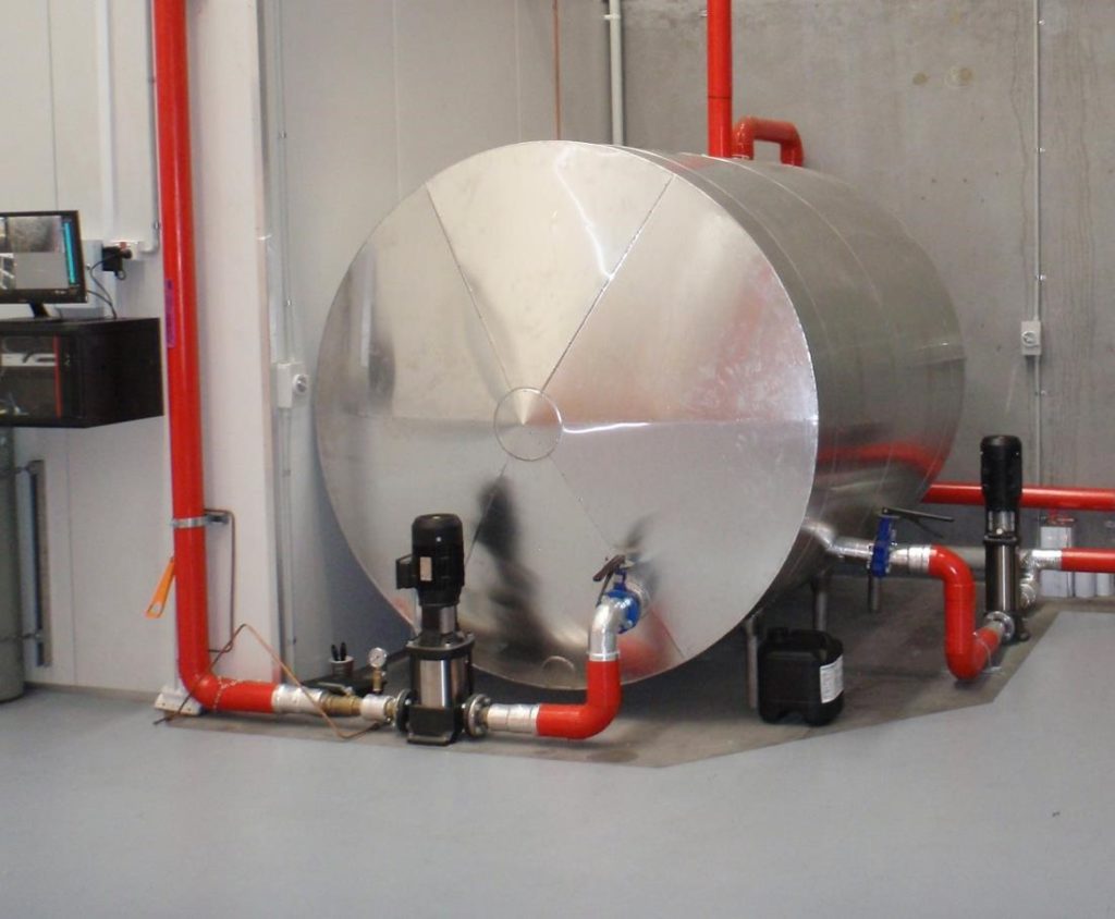
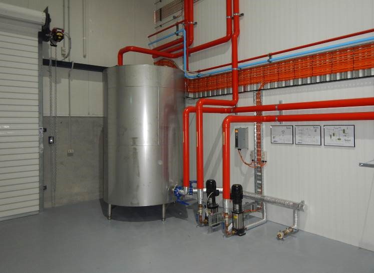
The freezer room’s subfloor and defrosting processes are managed using a warm glycol system circulated by pumps positioned in both the plant room and above the freezer area. An insulated 5000L stainless steel vat serves as the main glycol tank, heated by the discharge gas from the low-stage rack. This heat is transferred to food-grade glycol and distributed to the evaporators during defrost cycles via a small pump. Each of the four evaporators undergoes three defrosts every 24 hours, with dedicated glycol tubes replacing electric heater tubes in their circuitry. Glycol headers collect these tubes, ensuring sufficient heat reaches the drip trays and coil blocks to effect defrosting in approximately 15 minutes at a modest 45°C. Unlike electric defrost systems that generate significant heat release into the room, the glycol system retains heat within the coil block, minimizing post-defrost heat load and maintaining a more humid environment inside the freezer room.
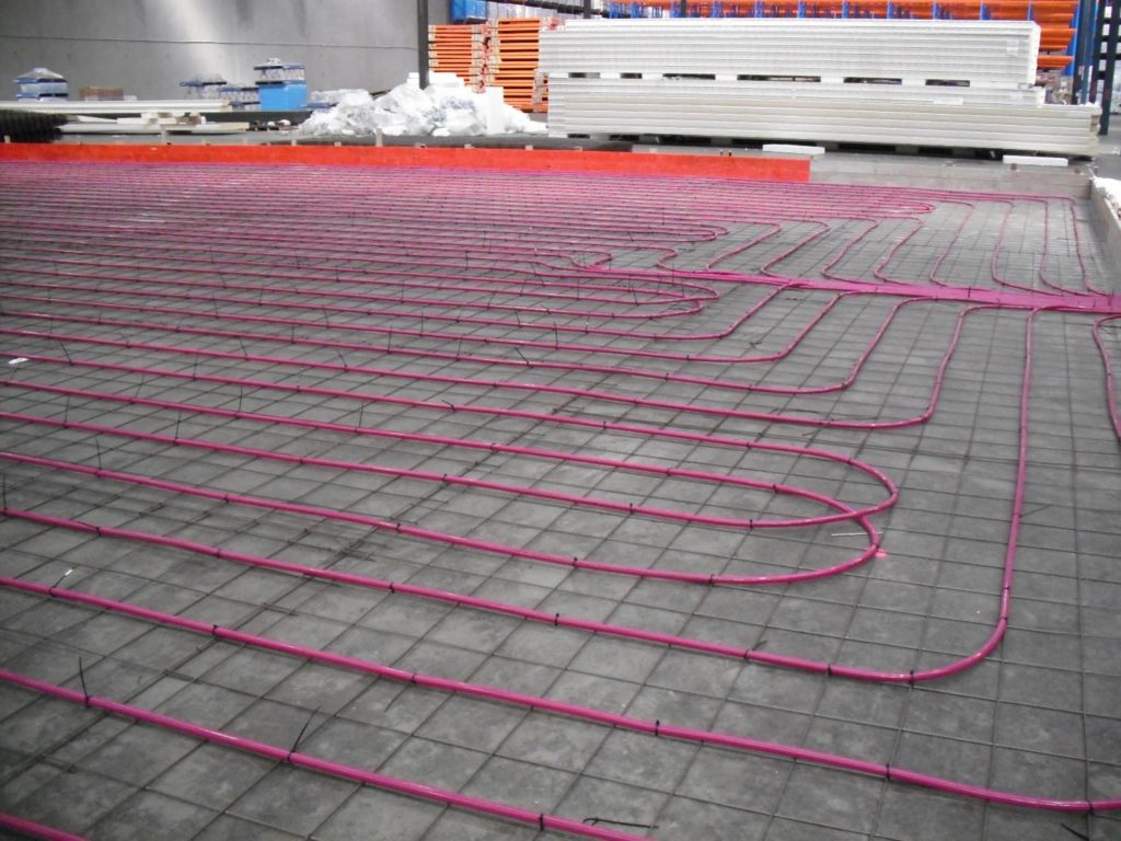
Given the site’s post-tensioned concrete slab, precautions were taken to avoid damaging embedded cables, necessitating the positioning of subfloor heating above the existing slab. The freezer room floor is heated separately by a glycol system linked to the defrost system, maintaining a floor temperature of 14°C. A small plate heat exchanger transfers heat from the defrost system glycol to the floor heating glycol on demand, regulated by a glycol solenoid at the pumping station above the freezer. This glycol system circulates through an insulated expansion tank and feeds into three floor heater manifolds, each equipped with nine nylon heater tubes totaling 120 meters in length per manifold, laid out in a grid pattern across the freezer floor to evenly distribute low-intensity heat. The entire system is encased in concrete slurry, insulated, and topped with a trafficable slab to support forklift operations while preventing frost heave in the subfloor beneath the freezer.
Operating Cost Comparison
The evaluation of the new trans-critical/sub-critical cascade CO2 system against a conventional R134a/CO2 system was prompted by the owner’s interest in leveraging the former as a marketing tool with major supermarket chains, key customers for their products. Detailed spreadsheets comparing equipment specifications and manufacturer-provided power consumption models were prepared to estimate operational costs for both options. While exact comparisons were challenging due to the singular installation of the previous system, the new system was favored for its potential energy efficiency benefits across different operating conditions.
The glycol floor heating system proved economically advantageous over conventional electric element sub-floor heating. Estimated savings indicated a substantial reduction in operating costs, with the glycol system utilizing a fraction of the energy required by electric heating elements. Specifically, the glycol system’s reduced heat load on the high stage and demand units further contributed to overall energy efficiency, translating to significant cost savings.
Moreover, the warm glycol defrost system demonstrated superior energy efficiency compared to electric defrost systems. The glycol-based defrosting process consumed considerably less power while also providing heat for the sub-floor, thereby minimizing additional heating costs. The substantial continuous power savings achieved by the glycol system underscored its economic viability, potentially saving thousands annually.
Additionally, the choice of CO2 as the refrigerant for both stages of the system not only reduced the system’s purchase and replacement costs but also significantly lowered its global warming impact compared to conventional refrigerants like R134a and R404A. This choice aligned with environmental sustainability goals, with the installed system showing a marked reduction in potential global warming impact.
The initial summer energy consumption data indicated comparable power usage between the new CO2/CO2 system and the previously installed R134a/CO2 system, despite expectations of higher summer energy use for the trans-critical system. This performance parity in summer usage hinted at the new system’s potential to outperform its predecessor during winter and other seasonal conditions, underscoring its enhanced efficiency and technological advancement over the earlier state-of-the-art system installed in 2011.