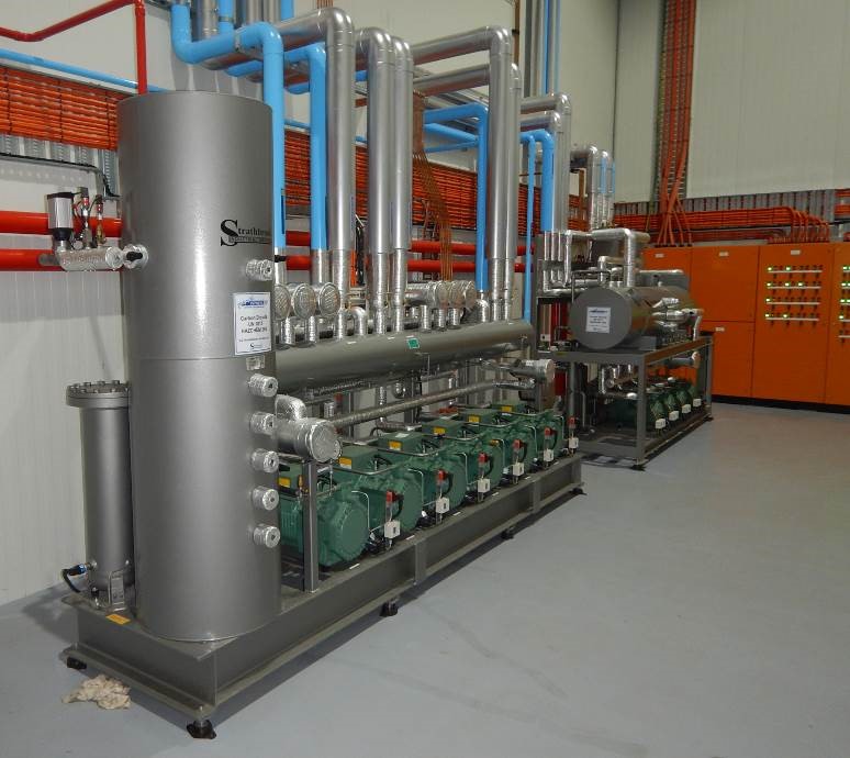
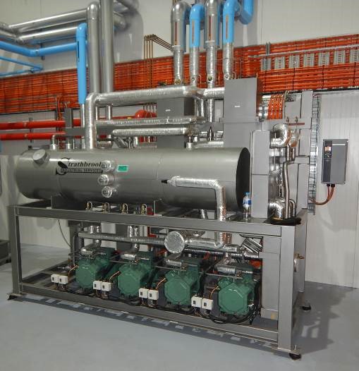
Freezer Room And Low Stage Pkg
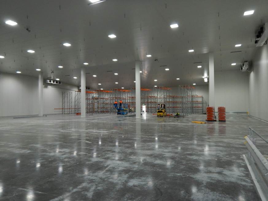
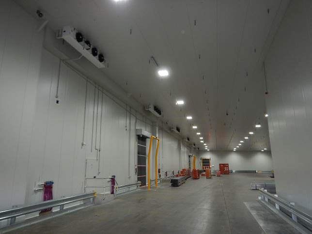
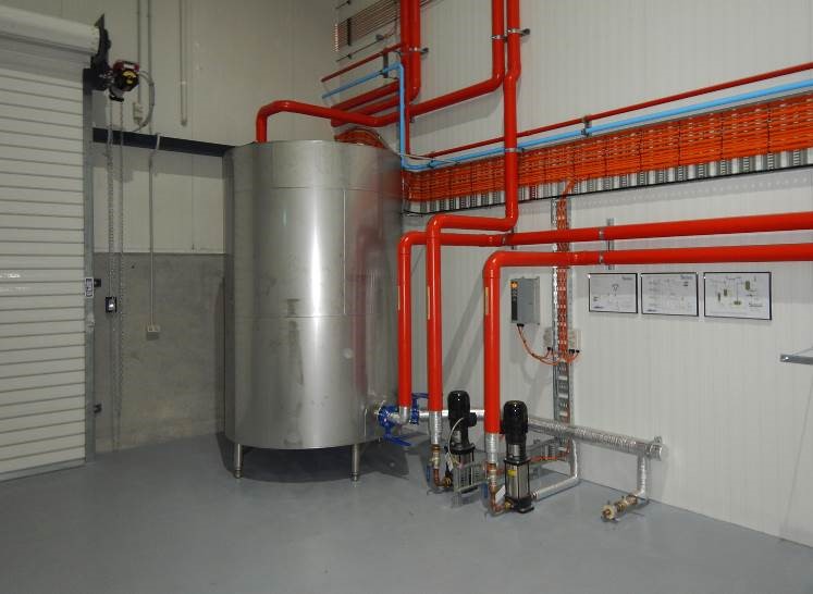
The site features a large -20°C freezer room measuring 59m x 21.5m x 10m (1268m²) with a cooling capacity of 120 kW, utilizing R744 (CO2) in four direct expansion evaporators equipped with Danfoss electronic TX valves. Designed and constructed by Strathbrook Industrial Services, the refrigeration package includes four Bitzer piston compressors operating in a single circuit, with variable speed control on the lead compressor for enhanced load matching. Additionally, the package incorporates an open flash intercooler/liquid receiver storing cold liquid CO2 at -5°C.
Heat recovery is integral to the system, utilizing warm glycol to defrost the freezer room, sourced from waste heat rejected by the refrigeration package. The discharge gas from the oil separator is condensed into liquid CO2 in the receiver vessel, with vapor directed into high-pressure plate heat exchangers for further condensation before gravity feeding back to the receiver. Inter-stage plate heat exchangers are supplied with direct expansion CO2 from the medium temperature high stage, forming a cascade cooling system.
The glycol defrost system, crucial for maintaining a 45°C glycol temperature, extracts heat from low stage discharge gas via a dedicated plate heat exchanger unit. Additional heat is transferred from discharge gas to suction vapor in a second pair of plate heat exchangers, ensuring optimal compressor operation by maintaining vapor temperatures between +1°C to +10°C. This temperature range prevents liquid droplets in the compressor oil system, enhancing efficiency and longevity. Control is managed by a suction gas temperature sensor and a discharge gas heating solenoid, optimizing heat recovery and operational conditions.
Chocolate Room / Staging & Dock / High Stage Pkg
The site includes a chocolate room spanning 59m x 22m x 10m (1300m²), maintained at 16°C by three direct expansion air defrost evaporators equipped with electronic TX valves. This area operates with a cooling capacity of 52 kW at -4°C, utilizing evaporators that help maintain a dry environment crucial for stored products.
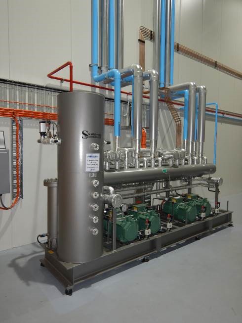
Adjacent to this, the staging and dock area features six direct expansion CO2 evaporators, providing a total capacity of 134 kW. These units share a suction group with the chocolate room system and are part of a split suction design with six Bitzer piston compressor machines from Strathbrook Industrial Services. Three compressors serve the high stage for the cascade freezer system, while the remaining three cater to cooling needs in the chocolate room and dock areas.
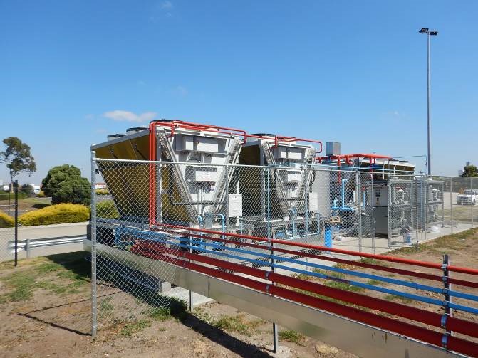
The system employs a fully transcritical CO2 setup with a maximum operating pressure of 130 bar. A Guntner Gas cooler with a 440 kW capacity is situated on the external condenser deck, equipped with 6 x 900mm EC fans and a stainless steel coil block featuring epoxy coated aluminum fin stock. Fan speed modulation via the Danfoss control system adjusts based on gas cooler exit temperature, optimizing fan power consumption especially in cooler ambient conditions. To further enhance performance during hot weather, a high demand water spray system reduces CO2 refrigerant temperatures, operating selectively for up to 400 hours annually to mitigate gas cooler corrosion risks.
Key components include a vertical liquid receiver managed by Danfoss electronic control valves to maintain precise system pressures. A suction header with a shell and tube heat exchanger warms returning suction vapor while subcooling liquid CO2, boosting overall system efficiency and optimizing compressor operations. Speed control on lead compressors enhances load matching capabilities, ensuring efficient performance across varying operational demands.
Chiller Room System
The chiller room is outfitted with a transcritical CO2 system featuring its dedicated gas cooler and eight Guntner direct expansion evaporators. Designed with future flexibility in mind, the chiller room can be converted to freezer duty if needed. It incorporates underfloor heating and warm glycol defrost evaporators specifically designed for freezer operations. Despite its independence from other systems, the chiller room shares similar design principles and operational characteristics to ensure cohesive functionality within the overall facility setup.
Staging Room With Dock Area
The staging area serves as a versatile workspace for date stamping, order assembly, and container unloading operations. Maintained at a temperature of +10°C, it is integrated with the same rack package that supports the high-stage freezer and the adjacent chocolate room.
High Deman Unit / Austrlaian Design Patent
Transcritical CO2 systems exhibit superior energy efficiency compared to conventional systems in lower ambient temperatures but become less efficient as ambient temperatures rise above approximately 24°C, where compressor capacity diminishes significantly—potentially by up to 50%. This typically necessitates additional compressor capacity in conventional transcritical systems for limited peak hours annually.
Strathbrook Refrigeration Services has developed a patented solution employing a separate high-demand refrigeration unit to cool the CO2 refrigerant leaving the gas cooler. This innovative approach allows the CO2 system to function similarly to its performance in cooler weather conditions. During periods of lower ambient temperatures, this high-demand unit operates intermittently, consuming no power and enabling the CO2 system to consistently operate in subcritical mode. This approach significantly reduces both the operational pressure of the system and the motor input power required for the high-stage compressors.
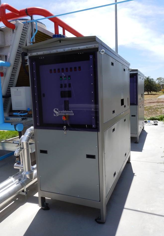
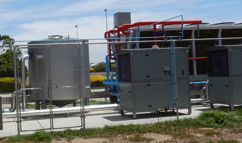
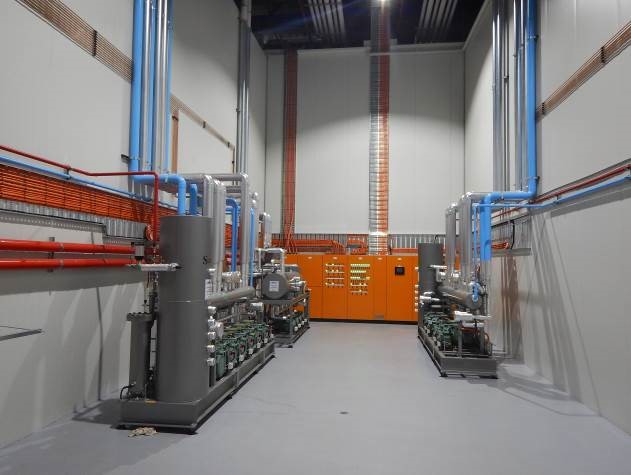
In this instance, the high-demand unit consists of two 200 kW water chillers utilizing Bitzer direct drive piston compressors operating on R717 (ammonia) in a direct expansion water-cooled system. These chillers supply water at 17°C to high-pressure plate heat exchangers positioned at the gas cooler outlet. The water then cycles through an insulated 9000 L storage tank before returning to the chiller, enabling extended operation periods during low-demand times and leveraging thermal storage in the tank to maintain consistent conditions.
Given the higher suction temperature of the ammonia chiller compared to the CO2 system, the operating Coefficient of Performance (COP) is notably elevated, enhancing overall system efficiency during high ambient conditions. The ammonia chillers operate with a Specific Cooling Power (SCP) of 40 kW per kg of ammonia refrigerant, achieving a COP of 9:1 at operating conditions of +12.5°C SST and 35°C SCT. These ammonia chillers, designed and constructed by Strathbrook Industrial Services, are complemented by a large air-cooled dry cooler that cools water used for condenser water cooling. Water sprays are employed to further cool the dry cooler during high ambient conditions, thereby maintaining low ammonia condensing temperatures effectively.
Control System
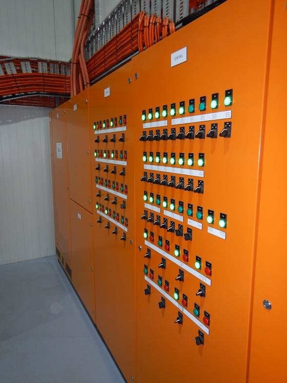
The system is overseen by a Danfoss 850 System controller, which employs electronic input/output cards to facilitate bidirectional communication with the microprocessor. This setup enables comprehensive monitoring and control of all system operations.
Dedicated computer cards manage essential components such as electronic motor control valves for the liquid receiver and electronic expansion valves. The controller integrates data from gas detectors, variable speed drives, room temperature sensors, and system pressures and temperatures. This integration allows for real-time monitoring of system performance both onsite and remotely via internet connectivity.
To ensure uninterrupted operation, an Uninterrupted Power Supply (UPS) is incorporated into the system. The UPS serves to maintain continuous power supply during outages, safeguarding the control system’s functionality and providing emergency power to critical cooling operations.
Electrical System
StratHbrook Electrical Services designed and constructed the electrical panel, incorporating the Danfoss control system along with various power and safety circuits.
The control system is programmed to respond to abnormal operating conditions, such as high-pressure events, by systematically shutting down devices. This precautionary measure helps stabilize the system before gradually restoring operations to normal. Consequently, the Danfoss controller autonomously manages events like power failures, minimizing the need for manual intervention by operators.
The Warm Glycol System
The freezer room subfloor heating and defrosting systems rely on circulating warm glycol managed by pumps situated in the plant room and above the freezer area. A 4000L insulated stainless steel vat houses the main glycol tank, which is heated by the discharge gas from the low-stage rack.
This heat, contained within a food-grade glycol solution, is utilized during defrost cycles facilitated by a small pump delivering heat to evaporators. Each evaporator undergoes three defrosts every 24 hours, facilitated by dedicated glycol tubes replacing traditional electric heaters. This method ensures efficient defrosting in approximately 15 minutes per cycle, minimizing the typical heat loss associated with electric defrost evaporators.
Operating at a defrost temperature of 45°C, the glycol system prevents excess heat from dissipating into the freezer room, thereby reducing the post-defrost load. Moreover, the lower defrost temperature prevents the evaporation of drip-down water, maintaining a dry environment within the freezer room.
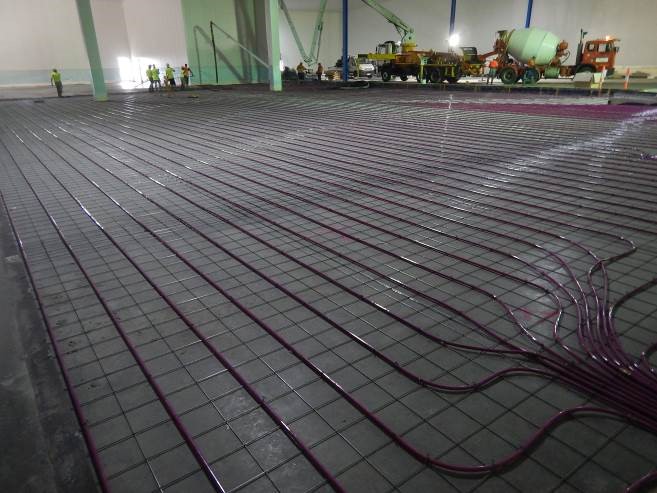
Given the site’s post-tensioned concrete slab floor, precautions were taken to avoid damaging embedded cables. Consequently, the subfloor heating was installed above the existing slab. A separate glycol circuit heats the freezer room floor to 14°C using heat from the CO2 liquid refrigerant line. A small plate heat exchanger transfers heat from water cooling the high-demand cooling system to the floor heating glycol as needed, regulated by a cycling water pump.
A glycol pumping station circulates the cooled glycol through an insulated expansion tank, then channels it into three floor heater manifolds. Each manifold distributes heat through nine 120m-long nylon heater tubes, totaling over 3km in length, arranged in a grid pattern to uniformly heat the freezer floor. The system, encased in concrete slurry and insulated, ensures frost heave prevention beneath the freezer while providing a durable surface for forklift traffic.
Plant Room And Pipework
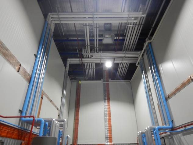
The pipework is meticulously installed using copper tubes and K65 high-pressure copper-iron alloy tubes encased within a robust PVC outer casing, filled with expanding foam to ensure structural integrity. Pipes are securely bracketed every 2 meters and color-coded for clear identification and maintenance purposes.
In the plant room, the floor is coated with three layers of epoxy for durability and cleanliness. Stainless steel drip trays are strategically fitted beneath the machines to effectively manage condensate and prevent water accumulation on the floor, ensuring a safe and hygienic environment.
Additionally, spare CO2 refrigerant is stored in a purpose-built bottle rack within the plant room, organized to facilitate easy access and inventory management. These measures underscore the commitment to meticulous design and operational efficiency in maintaining optimal conditions within the facility.
Operating Cost Comparison
The evaluation compared a transcritical CO2 system with a conventional R134a/CO2 setup, requested by the client who favored the transcritical/subcritical cascade system for its potential marketing advantages with major supermarket chains, key customers of their company.
Detailed spreadsheets were compiled to estimate power consumption for both options, highlighting the glycol floor heating system’s cost benefits over electric heating and the efficiency of the warm glycol defrost system compared to electric defrost. Significant power savings and operational efficiencies were noted, especially from recovering heat from the low stage and reducing high stage compressor run times by 20% each.
Using Carbon Dioxide in both stages resulted in reduced gas charges and a remarkable decrease in global warming potential compared to conventional refrigerants like R134a and R404A. The system’s performance was notably superior to the previous R134a/CO2 system in terms of power consumption, supported by efficient ammonia chillers and enhanced heat exchanger cooling via water sprays.
The current CO2/CO2 system, operational since 2014, outperformed the previous state-of-the-art system by 40%, with further improvements at the Salta Drive site achieving an additional 10% efficiency. Despite the new facility being significantly larger in volume, power consumption rose by only 80% compared to the smaller previous site, a testament to the system’s efficiency and design.
The ammonia chillers, equipped with variable speed drives (VSDs), suction unloaders, and precise control mechanisms, offered superior Coefficient of Performance (COP) due to optimal operating temperatures and advanced oil management systems. Each chiller’s low refrigerant charge expands its applicability to diverse settings previously deemed impractical.
Overall, the client expressed high satisfaction with the system’s performance and efficiency, underscoring its capability to meet stringent operational demands while minimizing environmental impact and operational costs.