Bega – Chullora
ARBS AWARDS – PROJECT EXCELLENCE 2020- 1 Worth St, Chullora Nsw

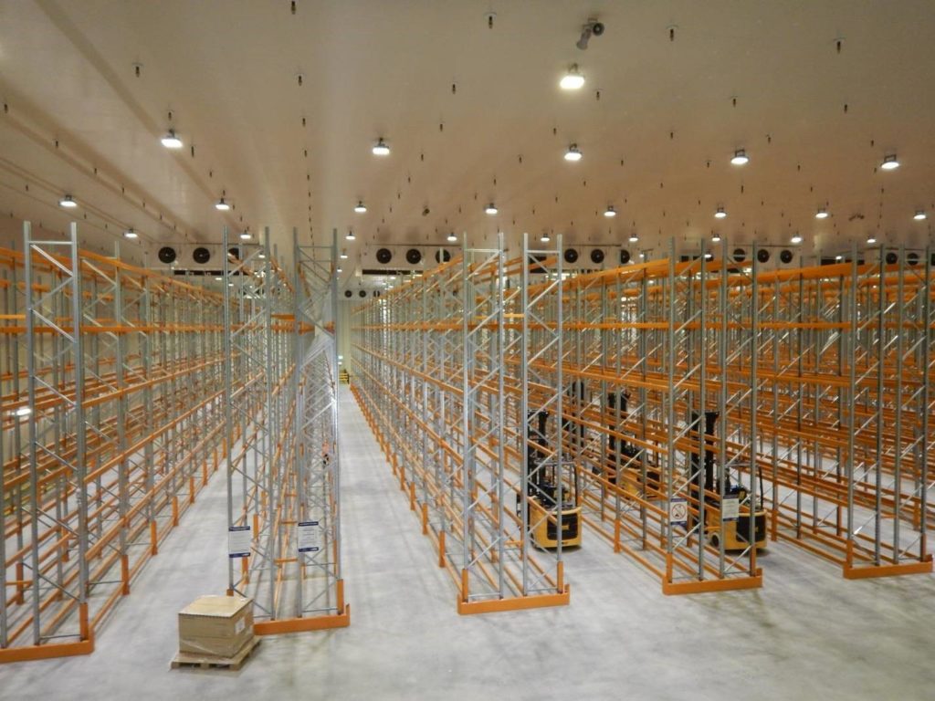
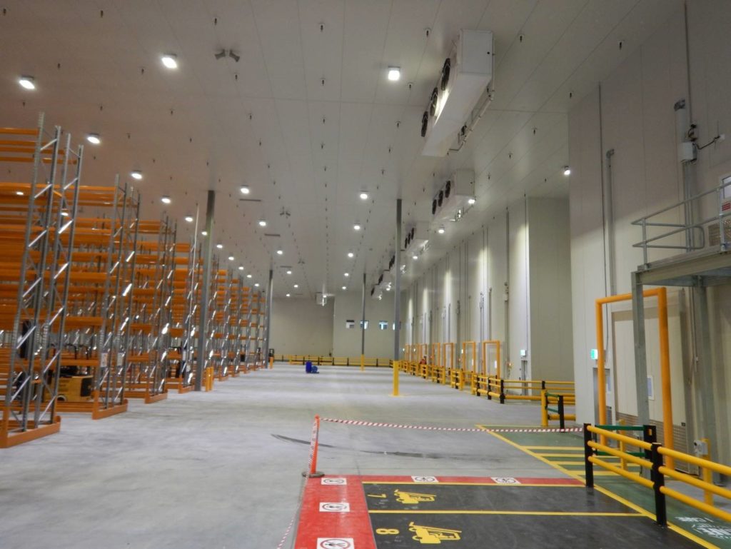
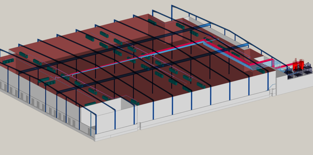
The cool room is approximately 90m x 90m x 10m high (7387m2) and holds 5646 pallets in the racking plus non racked storage.
The loading dock is approximately 15m x 90m x 10m high (982m2)
Room temperature 2 to 4 deg C
Refrigerant R717 (AMMONIA) with propylene glycol as a secondary fluid
Screw compressor Mycom JL170 with economizer sub cooler and variable
Valve: 603 kw Q 132 kw Pe @ -7 sst & 35 sct
COP 4.58 : 1
Cooling tower: Evapco MMT 110 900KW cooling capacity ( x 3 )
glycol coolers: Guntner 45kw Q @ 3 deg C glycol – 4 in & 2 out ( x 40 )
Bega Milk and Drinks Division enlisted Strathbrook Refrigeration Services for a comprehensive design and construction project to install a refrigeration system in their expansive new distribution center in Western Sydney. Bega provided key design directives such as their preferred refrigerant and the use of glycol as a heat transfer medium, aiming to minimize refrigerant charge, which served as foundational elements for the project’s design.
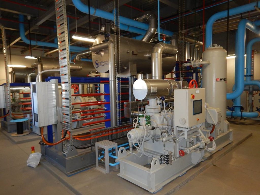
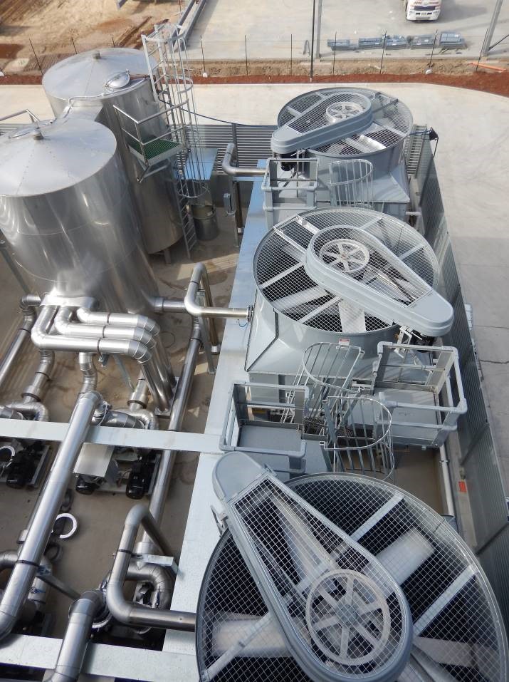
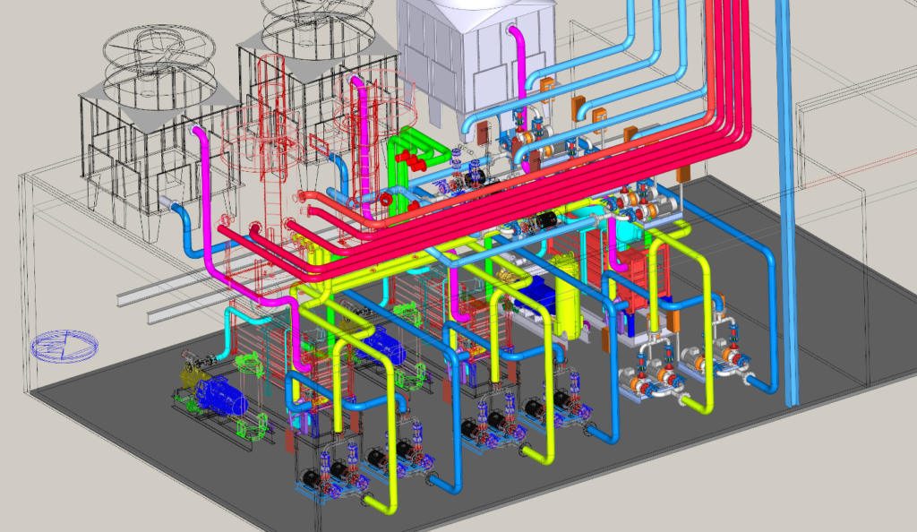
The cooling system implemented features three Mycom Ammonia screw compressor packages, each paired with a critically charged, flooded ammonia evaporator and surge drum. Located on the mezzanine deck above the compressors, dedicated evaporative water-cooling towers provide efficient heat dissipation for each package.
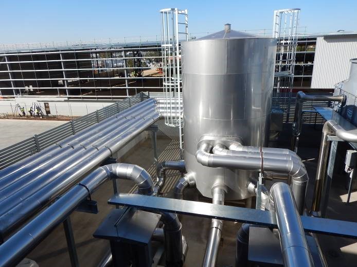
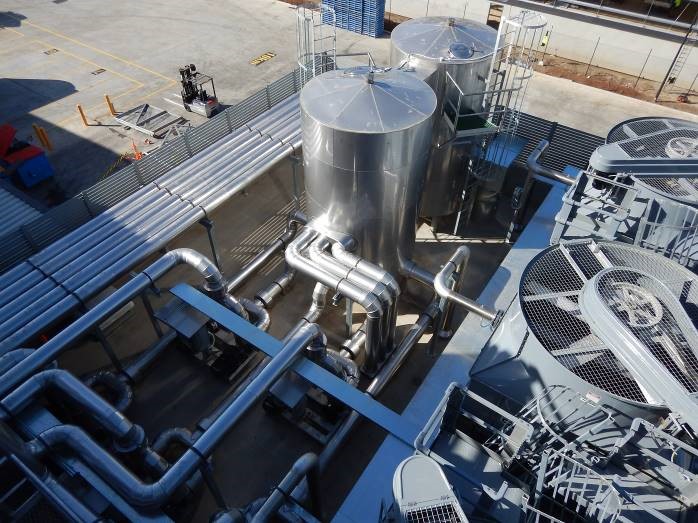
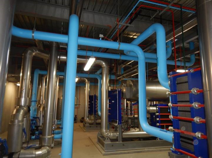
Operating independently, each package cools food-grade polypropylene glycol circulating throughout the facility. Two insulated 16,000-liter tanks made of 316-grade stainless steel act as supply and return reservoirs for the chilled glycol. These tanks not only facilitate glycol circulation through pumps but also provide thermal storage, ensuring consistent operation and preventing pump cavitation by maintaining positive suction head.
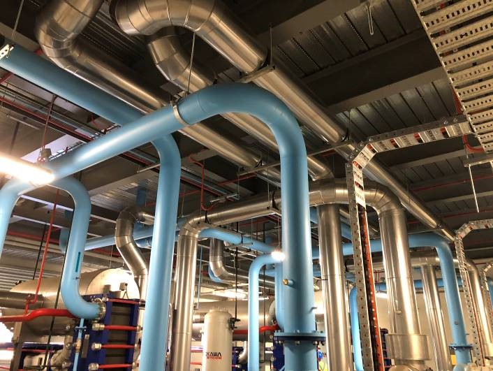
The main cooling areas, including a large cool room and loading dock, are equipped with forty Guntner glycol-to-air heat exchangers, arranged in multiple circuits to optimize cooling efficiency. The piping system comprises 200mm diameter stainless steel and copper tubes, insulated with metal-clad insulation filled with expanding foam.
This configuration allows for minimal ammonia charge in the compressor packages and enables individual systems to be isolated for maintenance without disrupting overall site cooling operations. Each compressor set features local onboard management via dedicated PLC control panels, while a Danfoss control system oversees and monitors pumps, blowers, fans, and other components in real-time, accessible both onsite and remotely.
This integrated approach ensures efficient and reliable operation of the refrigeration system, meeting Bega’s stringent operational requirements while minimizing environmental impact and operational costs.
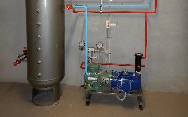
Three identical chiller packages, each with a refrigeration capacity of 607 kW at -7°C saturated suction temperature and 35°C saturated condensing temperature, operate at 3300 rpm with economizer liquid subcooling. Built by Mycom Australia, these packages feature vertical oil separators, 150 kW 2-pole motors with direct drive coupling and self-aligning coupling housing, water-cooled oil coolers, oil pumps and motors, as well as standard valves and controls for operational and servicing needs.
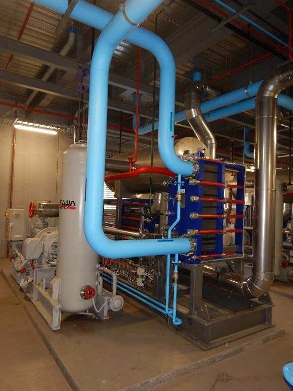
Each package includes an onboard electrical control panel with a PLC for monitoring and controlling compressor operations. The compressor speed is managed via a Danfoss Variable Speed Drive, optimizing energy efficiency. Condensers utilize gasket type plate heat exchangers supplied with cooling water from a dedicated tower located above the plant room.
Liquid ammonia leaving the condenser undergoes further subcooling in a second plate heat exchanger economizer positioned below the condenser. Subcooled ammonia liquid is directed by a high-side float to a low-side accumulator vessel, maintaining a consistent working level. From the accumulator, gravity-fed liquid ammonia enters the plate heat exchanger evaporator to cool glycol pumped through the system. Vapor from the heat exchanger is returned to the compressor for recompression.
An oil drain on the supply column facilitates the removal of oil from the system as needed. The accumulator vessel is equipped with safety features including a high-level float switch, level sight glasses, and necessary valves for operational integrity and maintenance.
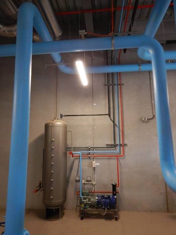
The proximity of compressor and accumulator skids facilitates easy servicing, with a refrigerant charge of 160 kg per package. Each package has a dedicated electrical panel ensuring control and safety, complemented by a permanent service receiver vessel hard piped to three service lines (discharge, suction, and liquid) connecting all packages. This setup allows efficient refrigerant transfer during maintenance.
Additionally, a small Bitzer ammonia pump-out compressor is integrated into the service system to evacuate residual ammonia during servicing, enhancing safety protocols. Service lines interconnect the oil systems, enabling rapid removal of the entire refrigerant charge in 120 seconds if required.
The system’s design allows for safe and efficient transfusion of suction, discharge gas, or liquid refrigerant to and from the service receiver and between chiller packages, facilitating streamlined maintenance procedures.
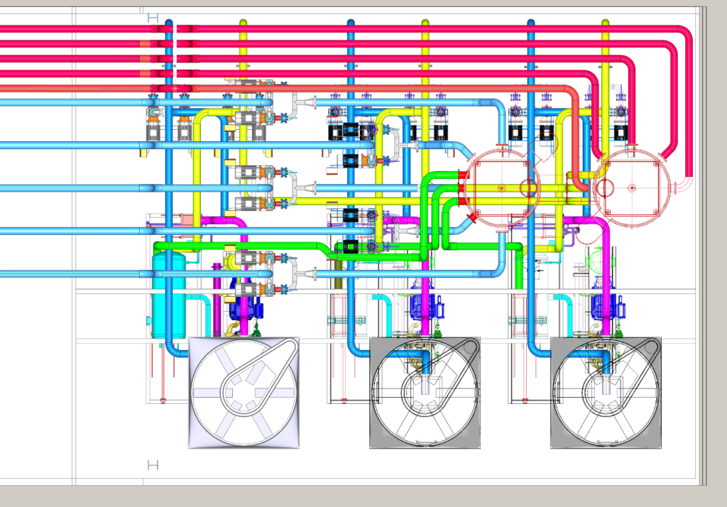
Three Evapco cooling towers, each with a capacity of 900 kW, are strategically positioned above the compressor sets to ensure each compressor package receives independent and efficient cooling water supply. These towers service the Alfa Laval plate condenser and oil cooler, contributing to the overall system efficiency.
Each tower is equipped with a single fan controlled by Variable Speed Drive (VSD) for optimal energy management. Additionally, there are run and standby pump sets, also equipped with VSD control, situated in the plant room beneath the towers. The 7.5 kW fan operation is regulated to maintain a consistent sump temperature within the tower, ensuring stable cooling performance. Simultaneously, the pumps are managed to maintain the condensing temperature within a precise operational range.
The 900 kW capacity of each tower is engineered to support energy-efficient operation across various conditions, including heavy load startup after plant shutdowns. This setup enhances system reliability and performance while prioritizing energy efficiency throughout operation.
Two 16,000-liter stainless steel glycol tanks, each measuring 2.4 meters in diameter and 4 meters in height (including dished ends and legs), form a crucial part of the refrigeration system’s glycol management infrastructure.
The supply tank receives glycol from the chillers through three 200mm supply pipes, storing it for distribution to the cool room via five 200mm delivery pipes controlled by pump sets. On the other hand, the return tank collects glycol from the cool room through five 200mm return lines, preparing it for recirculation back to the chillers for cooling.
These tanks are interconnected by a high-level spillway, ensuring that if one tank reaches a high level, excess glycol flows into the adjacent tank, preventing any loss. Constructed from 316-grade stainless steel, the tanks are insulated with 75mm of insulation and shielded by a stainless steel skin for durability and thermal efficiency.
To safeguard against glycol level faults, sensors are integrated into the system, capable of shutting down operations in such instances. Additionally, measures are in place to control the waste treatment process, ensuring that significant glycol losses are intercepted before being discharged.
This infrastructure design ensures reliable glycol storage and distribution, essential for the efficient operation and maintenance of the refrigeration system within the facility.
Forty Guntner glycol to air heat exchangers, organized into four groups of eight for the main room and one group of eight for the loading dock, play a crucial role in maintaining optimal temperature conditions within the facility.
Each heat exchanger draws glycol from the supply line at a flow rate of 5.7 liters per second, entering at -4°C and exiting at -2°C. The air flow volume is 15.1 cubic meters per second, with a velocity of 2.6 meters per second and an air throw reaching 45 meters.
Equipped with three fans, each heat exchanger operates at 2.7 amps, generating a noise level of 67 decibels at a distance of 3 meters. Positioned approximately 8 meters above the floor, these units are ceiling-mounted for efficient air distribution throughout the space.
An air-on temperature sensor continuously monitors the ambient air temperature. When the temperature is within 2°C of the set point, the fans automatically switch to low speed to conserve energy and reduce noise levels in occupied areas. If the temperature exceeds this threshold, the fans switch to high speed to rapidly lower the temperature before returning to low speed once conditions stabilize.
This sophisticated control system ensures precise temperature management while optimizing energy efficiency and maintaining comfort within the operational environment.
The refrigeration system employs predominantly TIG-welded stainless steel tubing, facilitated by an orbital TIG welder and pipe purge system for precise welding. Glycol pipes are shielded with a protective metal skin and insulated with 50mm of pumped expanding insulation.
Main glycol pipe runs originate from the plant mezzanine deck at high level, traversing through the ceiling space above the cool room. Within the plant room, each set of eight blowers is supplied via 200mm supply and return lines that bifurcate into two to evenly distribute coolant to four blowers on each side. Pipe sizing at each Tee is strategically managed to maintain consistent flow velocity, employing full-size Tees with downstream reducers to minimize pressure drops.
Final connections to the blowers consist of 2-1/2” copper tubes, integrating a three-way control valve for precise cooling adjustment at each unit. An air-on sensor provides a 0 to 10 volt signal to modulate the valve, diverting glycol flow around the cooling coil as the room temperature approaches the set point. This action reduces pressure drop in the pipe network and allows the delivery pump to operate at reduced speeds, enhancing overall energy efficiency.
Inside the plant room, glycol pipe work also utilizes stainless steel with metal-clad poured insulation, ensuring optimal thermal efficiency. In contrast, condenser water pipes are left uninsulated to maintain efficient heat transfer characteristics.
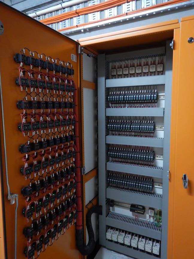
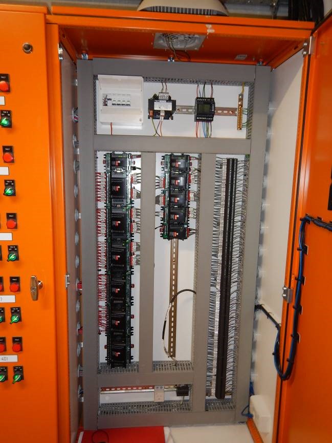
The electrical panels dedicated to the chiller systems are housed in a separate control room within the plant facility, ensuring they are isolated from the ammonia environment. This room is constructed with fire-rated materials, featuring a flexible glass window that provides visual access to the plant operations from inside. This setup not only meets regulatory requirements but also minimizes the need for extensive shunt trip protection across equipment.
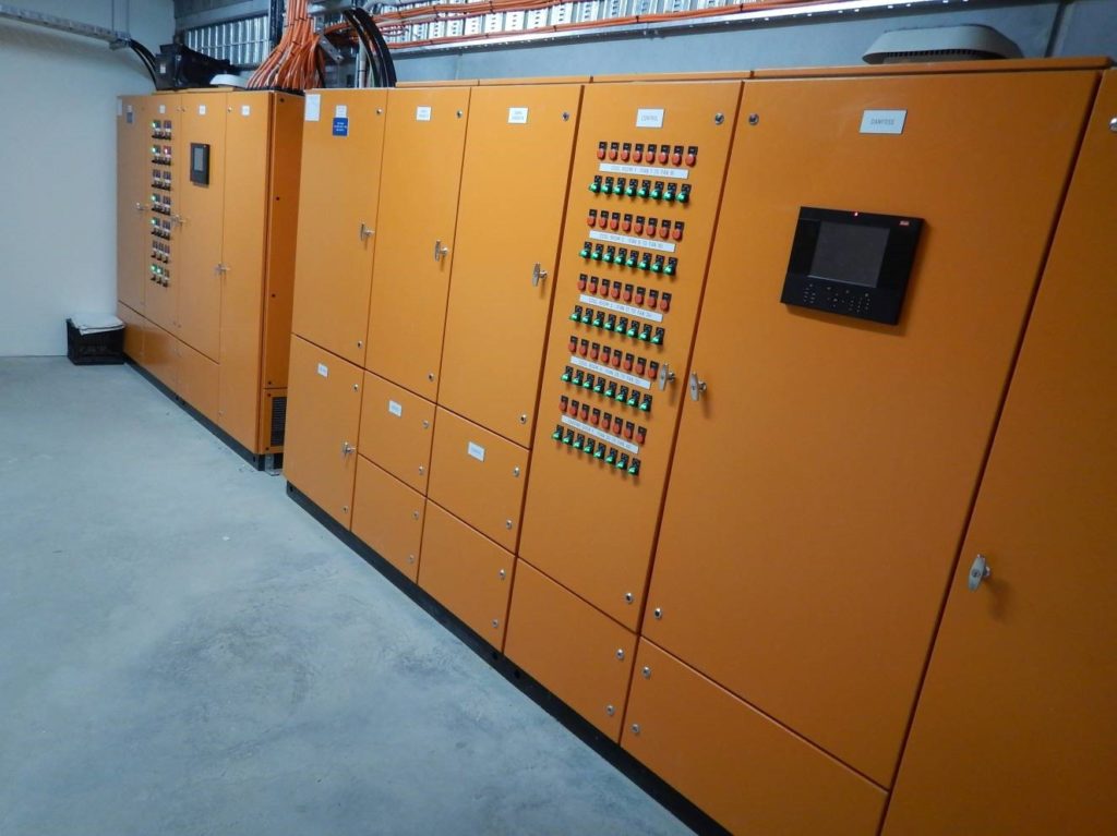
Each of the three compressor panels oversees the operation of one chiller system, managing the compressor, condenser, evaporator, cooling tower fans, pumps, and the compressor variable speed drive (VSD). Positioned in a small electrical room adjacent to the main compressor area, these panels allow operators and technicians to monitor plant activities through the flexible glass window.
The primary electrical distribution panel is situated in an upstairs switch room directly above the plant room. This panel supplies power to the three chiller panels and houses the site’s control system, along with contactors and overloads for the VSD-controlled glycol pumps. Because the major loads are managed by VSDs, the panel does not require power from the power factor correction panel, as VSDs inherently provide corrected voltage to each device.
Additionally, a second electrical panel within the upstairs switch room is dedicated to controlling the fan motors for the Guntner coolers and the exhaust fans within the plant room.
The project design involved meticulous engineering and planning to ensure the system achieved top-tier performance standards. Each component was carefully selected and engineered to optimize performance, reliability, and site safety.
The owner’s stringent energy-saving requirements served as a foundation for the design team, who expanded on these demands by integrating cutting-edge technologies. This approach not only met but exceeded expectations, setting a new standard for large-scale cold storage facilities in 2020.